Installing NERO-BLIND
This module is used to control the motor of blinds, rollers, shades, venetian blinds, etc. The module can be controlled either through a NEXUS-NERO Communications Gateway or through a wall switch.
Precise positioning is supported for motors equipped with mechanical or electronic end switches.
The NERO-BLIND module measures the power consumption of the motor and supports connection of a digital temperature sensor.
It is designed to act as repeater in order to improve range and stability of the Z-Wave Network.
1. INSTALLATION
-
Before the installation, disconnect the power supply
-
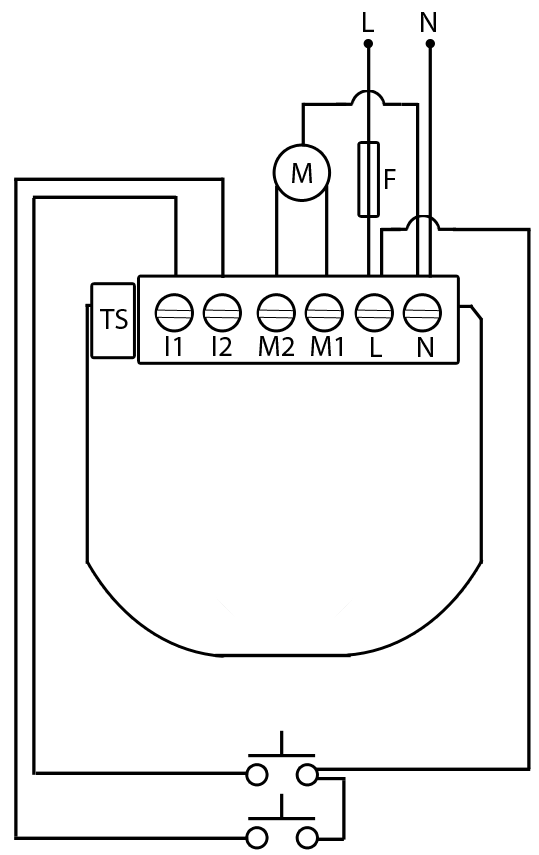
Connect the module according to electrical diagram
-
Locate the antenna as far as possible from metal elements
-
Do not shorten the antenna
1.1 Supported Switches
The NERO-BLIND module only supports 2-Button Manual Control.
1.2 M1 and M2 Terminals
Due to the wide variety of motorized blinds the up and down terminal orientations vary between brands and models. When wiring the terminals to the NERO-BLIND, it is advisable to sync in the device and control the blinds via the NERO software before securing the switch plate to the wall. If the “UP” command from the software corresponds to the “DOWN” action of the motor, simply swap the connections on terminals M1 and M2.
1.3 Motor Compatability
The motors that are compatible with the NERO-BLIND are known as "standard motors" in the window covering industry. They are bi-directional 4-Wire (2 Hot, 1 Neutral, 1 Ground) motors with internal limit switches. Typically the relays inside the controllers can handle any size window covering motor. One hot wire runs the shade in one direction, the other is for the other direction, cutting power stops the shade or when the shade hits its set limit an internal switch disconnects power to that directional wire (stopping the motor).
Load sensing on some controllers will sense when a motor reaches its limit and stops, and it will return the relay to a neutral position and report confirmation of stop through the software.
1.4 Overcurrent Protection Fuse
NERO-BLIND must be protected by an over current protection fuse not rated any higher than 4A as illustrated in the wiring diagram.
Danger of electrocution!
-
Module installation requires a great degree of skill and may be performed only by a qualified and licensed electrician.
-
Even when the module is turned off, voltage may be present on its terminals. Any works on configuration changes related to connection mode or load must always be performed with a disconnected power supply.
Note: Do not connect the module to loads exceeding recommended values. Connect the module only in accordance to the below diagram. Improper connections may be dangerous.
2. WIRING DIAGRAMS
2.1 Electrical diagram 240VAC
N Neutral
L Live
M1 Output for motor connection M1
M2 Output for motor connection M2
I2 Input for switch to control M2
I1 Input for switch to control M1
TS Terminal for digital temperature sensor
Maximum Ratings 240VAC
Output current (resistive load) 4A
Output power (resistive load) 920W

Technical Specifications
